Arduino Frequency Counter with 16×2 LCD Display
You can download our e-book ‘Learn Arduino from Scratch’ from this link
Recently, a friend of mine had an issue with his car’s ECU and needed a frequency counting device. The solution was a device to determine the pulse frequency emitted by the ECU against the rev counter.
So, the device had to have the ability to read digital pulses, between 1v – 5v, which are then interpreted by a digital pin on the arduino as HIGH and LOW pulses. Then outputs the frequency in hz/khz on the LCD display.
Hardware
1x Arduino Uno (ebay)
1x 16×2 LCD SPI (not the I2C) (ebay)
3x jumper wires (ebay)
The Setup
I had bought a 16×2 LCD and never actually did anything with it, so it was about time 🙂 The LCD was in the form of a shield compatible with Arduino Uno.
I snapped the LCD onto the Arduino and attached a jumper wire to analog pin A5. I am still using digital input in my code but since almost all digital pins were taken by the LCD I’ve decided to utilize an analog pin.
Now, the device can be powered via the USB port, the jack pin or the VIN. I am using the VIN here as I had no jack available and I was using the car’s supply (roughly 12v-14v).
Circuit
If using the LCD shield you can skip this part, but if you don’t have a shield here are the connections that are needed.
LCD ———-Arduino
RS ———– 12
Enable ——11
D4 ———– 5
D5 ———– 4
D6 ———– 3
D7 ———– 2
R/W ——— GND
VSS ———- GND
VCC ———- +5V
Add 10Kohm resistor between +v5 and GND
Plug in the +12v of the battery in Arduino VIN pin and GND of the battery to Arduino GND.
Finally the A1 pin jumper wire to the source of the frequency to be measured.
NOTE: In my case both the ECU and the Arduino had their GND connected (at the GND Terminal of the battery).
The Sketch
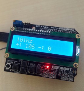
The sketch is fairly simple. We will display 3 values on screen. The current frequency, the max frequency and the min frequency, updating every second. The min and max are reset every 5 minutes.
We are using the LiquidCrystal.h which is included in the Arduino IDE installation, so you don’t need to add anything.
Source code: Download here
Limitations
We tested the device using another arduino (which probably it’s not the best thing to do) and found that up to 50khz the device had an error of around +/- 3% so it’s actually pretty good.
Beyond 50khz, the error started to rise and became very inaccurate. So our suggestion is to use it only for frequencies under 50khz.


hay, can you give me the scematic? thankyou…
This is a straightforward approach and certainly usefull for measuring low frequency signals. I have been working on an Arduino frequency counter since last november and I could see that it gets pretty much complicated if you want to reach a very good accuracy and particularly in high frequencies. Some of the major concerns are
1) One canno’t measure low frequencies (as you did and it seems it is limited to about 50 Khz in this cas) and high frequencies using the same method. You can use freqMeasure library to measure the period of lox frequency signals and freqCount library to mesaure high frequency signals
2) Low frequency signals have to be fed to the microcontroller under high impedance otherwise it would ring. But high frequencies need much lower impedance or the will vanish… So essentially frequency bands must be treated in separated electronic circuits, maybe using one unique microcontroller for the measurement.