The ESP8266 – A Tutorial – Part 1 Environment Setup
You can download our e-book ‘Learn Arduino’ from this link
Introduction
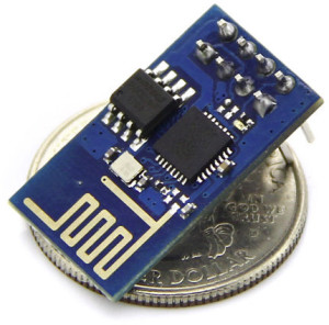
The Internet of Things is a relatively new concept in the world of electronics. It was also quite expensive and maybe even unreachable by some hobbyists. The introduction of the ESP8266 changed that perception forever. Being first designed as a simple Serial WiFi adapter; today it is the most common IoT device among electronic hobbyists and hackers alike. The ESP is cheap, small, powerful and easy to program as you shall see in a jiffy. This tutorial will focus on the ESP-01 model.
There are many versions and different boards with the ESP8266, in this tutorial we will focus on the most common and cheapest model the ESP-01. This little board comes pre-installed with the original firmware which allows it to act as a Serial WiFi Module, however, this firmware is of little use to us. Together we are going through the process of transforming a WiFi Module into a fully flagged stand alone WiFi enabled Arduino.

First and foremost it is very important to note that the ESP8266 is not 5V tolerant. VCC and all other pins must be fed 3.3V only. Apart from that the ESP-01 cannot be programmed directly because it does not have a USB port and is not even RS232 compatible. We will need an FTDI 3.3V like the one below.

Now all you need are some jumper wires to connect the ESP with the FTDI.
Connections
- ESP-01 FTDI
- VCC VCC (remember 3.3V only)
- GND GND
- RX TX
- TX RX
- CH_PD VCC
- GPIO 0 GND (only used to flash the module with new software)

Done that, grab a USB cable and plug it in the FTDI and your PC.
Environment Setup
Prerequisites: Latest Arduino IDE ( link )
- Start Arduino IDE
- Go to File > Preferences.
- Enter
http://arduino.esp8266.com/stable/package_esp8266com_index.jsonin Additional Board Manager URLs field. You can add multiple URLs, separating them with commas. - Open Boards Manager from Tools > Board menu and find esp8266 platform.
- Select the latest version
- Click install button.
- Go to Tool > Boards and select Generic ESP8266
Testing
All set and ready to code. Make sure your ESP is plugged in. Go to Tools > Port and select the COM port which the ESP is connected to. Then paste the code below. It’s a simple blink program to test our setup.
void setup() {
  pinMode(LED_BUILTIN, OUTPUT);     // Initialize the LED_BUILTIN pin as an output
}

// the loop function runs over and over again forever
void loop() {
  digitalWrite(LED_BUILTIN, LOW);   // Turn the LED on (Note that LOW is the voltage level
                                    // but actually the LED is on; this is because
                                    // it is active low on the ESP-01)
  delay(1000);                      // Wait for a second
  digitalWrite(LED_BUILTIN, HIGH);  // Turn the LED off by making the voltage HIGH
  delay(2000);                      // Wait for two seconds (to demonstrate the active low LED)
}
If the LED blinks, you’re done. The setup is complete and you can start experimenting with your ESP-01. Stay tuned for Part 2 of this tutorial 🙂


Thanks. I’m waiting for next tutorial. For example, how to connect esp8266 to Wifi hotspot and get data from an URL.
Hai Guys i’m new with ESP8266 i tried to turn On Led with ESP8266 module but i failed several times following the tutorials from internet most of them says i need to flash the ESP and i cant succeed in flashing the ESP to will you able to provide a simple tutorial to acheive my task and start working with ESP (Without FTDI hardware)
You will need an FTDI to connect the ESP8266 to a USB port. Flashing is done automatically with the Arduino IDE every time you upload new code.
Can an Arduino be set up to behave as a FTDI to program the ESP?
Hi
I cant get this to work. Triple checked my wires.
What happens with wires connected exactly as your wiring illustration during upload is a blue led on the ESP8266 is flashing, as if receiving data from the FTDI.
After a while it stops flashing, and the arduino IDE outputs this:
“Sketch uses 222129 bytes (51%) of program storage space. Maximum is 434160 bytes.
Global variables use 31496 bytes (38%) of dynamic memory, leaving 50424 bytes for local variables. Maximum is 81920 bytes.
Uploading 226272 bytes from /tmp/arduino_build_607108/Blink.ino.bin to flash at 0x00000000
…………………..”
Then the IDE says : “done uploading”
But theres no led flashing on the ESP as to indicate that the upload worked!
Tried also with and without the ground wire from ftdi ( that cant work obviously). And with and without the wire drawn as orange on your illustration on the wiring setup (also connected to ground ftdi).
Also verified that the ESP8266 gets 3.3 V and not 5 V
I have not yet changed any of the default arduino ide settings for the generic ESP8266 module (flash mode, flash frequenzy etc.).
Any suggestions?
If the led doesn’t flash, try use a external power supply.
It’s works for me.
remember to connect the ground from the power supply and the usb power.